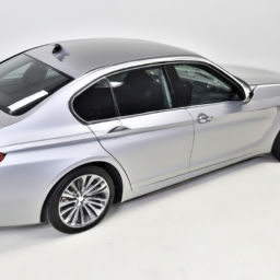
Replacing a ball joint on a BMW 535d F10 LCI may seem daunting if you have little mechanical experience, but with the right tools and a step-by-step guide, it can be manageable. click here for more details on the download manual…..
- 535d #straightpipe #stage2 #mapro
- Bmw F10 535d 400 Ps
Here’s a simplified explanation of the process:
### Tools and materials Needed:
1. **Tools:**
– Jack and jack stands
– Lug wrench
– Socket set
– Wrench set
– Ball joint separator tool (also known as a pickle fork)
– Torque wrench
– Hammer
– Pliers
– Screwdriver
– Safety glasses and gloves
2. **Parts:**
– Replacement ball joint (OEM recommended for best fit)
– Grease (if needed for the new ball joint)
### Step-by-Step Guide:
#### 1. Preparation:
– **Safety First:** wear safety glasses and Gloves to protect yourself.
– **Space:** Work in a well-lit area with enough space to move around the vehicle.
#### 2. Lift the Vehicle:
– **Loosen Lug Nuts:** Before lifting the vehicle, use the lug wrench to slightly loosen the lug nuts on the front wheel where the ball joint will be replaced.
– **Jack the Car Up:** Use the jack to lift the front of the car. Make sure to lift it from the designated jacking point.
– **Secure with Jack Stands:** Once the car is lifted, place jack stands under the vehicle for safety. Never work under a car supported only by a jack.
#### 3. remove the Wheel:
– **Take Off the Wheel:** Completely remove the loosened lug nuts and take off the wheel to access the suspension components.
#### 4. Locate the Ball Joint:
– **Identifying the Ball Joint:** The ball joint is typically located at the lower control arm, connecting it to the wheel hub assembly.
#### 5. remove the Old Ball Joint:
– **Disconnect Components:** If there are any components (like a brake line or sway bar) connected to the area around the ball joint, carefully remove or disconnect them.
– **Use the Ball Joint Separator:** Insert the ball joint separator tool between the ball joint and the control arm. Gently tap the tool with a hammer to separate the joint from the control arm.
– **Unbolt the Ball Joint:** Once separated, remove the bolts securing the ball joint to the control arm. Keep track of the bolts, as you will need them for the new joint.
#### 6. install the New Ball Joint:
– **Position the New Joint:** Align the new ball joint with the holes in the control arm and press it into place.
– **Secure the Ball Joint:** Use the bolts you removed earlier to secure the new ball joint. Tighten them until they are snug but do not fully tighten yet.
– **Torque to Specification:** Use a torque wrench to tighten the bolts to the manufacturer’s specifications (check your repair manual for the exact torque value).
#### 7. Reassemble Components:
– **Reattach Any Removed Components:** Reconnect any components that were removed to access the ball joint.
– **Reinstall the Wheel:** Place the wheel back onto the hub and hand-tighten the lug nuts.
#### 8. Lower the Vehicle:
– **Remove Jack Stands:** Carefully lower the vehicle back to the ground and remove the jack stands.
– **Tighten Lug Nuts:** Use the lug wrench to tighten the lug nuts in a crisscross pattern to ensure even tightness.
#### 9. Final Checks:
– **Check Everything:** Make sure all tools are removed from the work area, and double-check that all connections are secure.
– **Test Drive:** Take the car for a short drive to ensure everything feels right.
### Conclusion:
Ball joint replacement requires careful attention to detail and safety. If at any point you feel uncomfortable with the process, don’t hesitate to reach out to a professional mechanic for assistance. Always refer to your vehicle’s service manual for specific instructions and torque specifications.
The starter is a crucial component of an internal combustion engine, responsible for initiating the engine’s operation. Essentially, it is an electric motor that engages when the driver turns the ignition key or presses the start button. The primary function of the starter is to crank the engine, creating the necessary rotational motion to facilitate combustion.
When the ignition is activated, a small amount of electrical current flows from the battery to the starter motor. This current energizes the motor, causing it to spin rapidly. The starter is connected to the engine’s flywheel, and as it turns, it engages a gear mechanism called the pinion gear which meshes with the flywheel’s ring gear. This engagement allows the starter to turn the crankshaft, initiating the engine’s cycle.
Once the engine starts and runs on its own, the starter disengages automatically, preventing damage to the components. A starter typically consists of several parts, including the motor, solenoid (which acts as a switch), and the drive mechanism. Over time, starters can wear out due to heat, mechanical stress, and electrical fatigue, leading to issues like slow cranking or failure to start. Regular maintenance and timely replacement of a faulty starter are essential for ensuring reliable engine performance and vehicle dependability.